Product Description
Flexible flex Fluid Chain Jaw flange Gear Rigid Spacer PIN HRC MH NM universal Fenaflex Oldham spline clamp tyre grid hydraulic servo motor shaft Coupling
Product Description
The function of Shaft coupling:
1. Shafts for connecting separately manufactured units such as motors and generators.
2. If any axis is misaligned.
3. Provides mechanical flexibility.
4. Absorb the transmission of impact load.
5. Prevent overload
We can provide the following couplings.
| Rigid coupling | Flange coupling | Oldham coupling |
| Sleeve or muff coupling | Gear coupling | Bellow coupling |
| Split muff coupling | Flexible coupling | Fluid coupling |
| Clamp or split-muff or compression coupling | Universal coupling | Variable speed coupling |
| Bushed pin-type coupling | Diaphragm coupling | Constant speed coupling |
Company Profile
We are an industrial company specializing in the production of couplings. It has 3 branches: steel casting, forging, and heat treatment. Main products: cross shaft universal coupling, drum gear coupling, non-metallic elastic element coupling, rigid coupling, etc.
The company mainly produces the industry standard JB3241-91 swap JB5513-91 swc. JB3242-93 swz series universal coupling with spider type. It can also design and produce various non-standard universal couplings, other couplings, and mechanical products for users according to special requirements. Currently, the products are mainly sold to major steel companies at home and abroad, the metallurgical steel rolling industry, and leading engine manufacturers, with an annual production capacity of more than 7000 sets.
The company’s quality policy is “quality for survival, variety for development.” In August 2000, the national quality system certification authority audited that its quality assurance system met the requirements of GB/T19002-1994 IDT ISO9002:1994 and obtained the quality system certification certificate with the registration number 0900B5711. It is the first enterprise in the coupling production industry in HangZhou City that passed the ISO9002 quality and constitution certification.
The company pursues the business purpose of “reliable quality, the supremacy of reputation, commitment to business and customer satisfaction” and welcomes customers at home and abroad to choose our products.
At the same time, the company has established long-term cooperative relations with many enterprises and warmly welcomes friends from all walks of life to visit, investigate and negotiate business!
How to use the coupling safely
The coupling is an intermediate connecting part of each motion mechanism, which directly impacts the regular operation of each motion mechanism. Therefore, attention must be paid to:
1. The coupling is not allowed to have more than the specified axis deflection and radial displacement so as not to affect its transmission performance.
2. The bolts of the LINS coupling shall not be loose or damaged.
3. Gear coupling and cross slide coupling shall be lubricated regularly, and lubricating grease shall be added every 2-3 months to avoid severe wear of gear teeth and serious consequences.
4. The tooth width contact length of gear coupling shall not be less than 70%; Its axial displacement shall not be more significant than 5mm
5. The coupling is not allowed to have cracks. If there are cracks, it needs to be replaced (they can be knocked with a small hammer and judged according to the sound).
6. The keys of LINS coupling shall be closely matched and shall not be loosened.
7. The tooth thickness of the gear coupling is worn. When the lifting mechanism exceeds 15% of the original tooth thickness, the operating mechanism exceeds 25%, and the broken tooth is also scrapped.
8. If the elastic ring of the pin coupling and the sealing ring of the gear coupling is damaged or aged, they should be replaced in time.
Certifications
Packaging & Shipping
/* January 22, 2571 19:08:37 */!function(){function s(e,r){var a,o={};try{e&&e.split(“,”).forEach(function(e,t){e&&(a=e.match(/(.*?):(.*)$/))&&1
| Standard Or Nonstandard: | Nonstandard |
|---|---|
| Shaft Hole: | 19-32 |
| Torque: | <10N.M |
| Bore Diameter: | 19mm |
| Speed: | 8000r/M |
| Structure: | Rigid |
| Samples: |
US$ 999/Piece
1 Piece(Min.Order) | |
|---|


Can HRC Couplings Handle Misalignment Between Shafts?
HRC (Highly Resilient Coupling) couplings are designed to handle a certain degree of misalignment between shafts, making them suitable for applications where alignment issues may arise. These couplings can accommodate both angular and parallel misalignment to some extent, providing flexibility and resilience in mechanical systems.
The flexibility of HRC couplings is primarily due to their construction, which typically includes a flexible element made of rubber or other elastomeric materials. This flexible element sits between two metal hubs and absorbs misalignment by allowing a certain degree of movement.
There are generally two types of HRC couplings based on their ability to handle misalignment:
- Single Flex HRC Couplings: These couplings can accommodate angular misalignment but have limited capability to handle parallel misalignment. They are suitable for applications where angular misalignment is more prevalent.
- Double Flex HRC Couplings: These couplings are designed to handle both angular and parallel misalignment to a greater degree than single flex couplings. They offer increased flexibility and can handle more demanding misalignment conditions.
It is important to note that while HRC couplings can handle misalignment, they do have limits. Excessive misalignment beyond their specified range can lead to premature wear and failure. It is essential to follow the manufacturer’s guidelines and ensure that the coupling is properly installed and aligned to prevent unnecessary stress on the flexible element.
For applications with significant misalignment or where precise alignment is critical, other types of couplings like flexible couplings with elastomeric elements, gear couplings, or disc couplings may be more suitable. Engineers and designers should carefully assess the misalignment requirements of their specific application and choose the appropriate coupling type accordingly.

How Does an HRC Coupling Handle Angular, Parallel, and Axial Misalignment?
An HRC (Highly Resilient Coupling) is designed to handle various types of misalignment, including angular, parallel, and axial misalignment. The coupling’s unique construction allows it to provide flexibility while transmitting torque between two shafts. Here’s how it handles each type of misalignment:
1. Angular Misalignment: Angular misalignment occurs when the axes of the connected shafts are not perfectly aligned. The HRC coupling can accommodate this misalignment due to its flexible element, typically made of synthetic rubber or polyurethane. The rubber element can bend and flex, allowing the coupling to compensate for slight angular deviations between the shafts. This helps to reduce stress on the connected equipment and the coupling itself.
2. Parallel Misalignment: Parallel misalignment happens when the shafts are not perfectly aligned side by side. The HRC coupling’s rubber element can also tolerate small amounts of parallel misalignment. As the shafts move slightly in parallel, the rubber element flexes to maintain the torque transmission between the shafts. However, excessive parallel misalignment should be avoided to prevent premature wear on the coupling.
3. Axial Misalignment: Axial misalignment occurs when the ends of the shafts move closer together or farther apart. The HRC coupling can accommodate limited axial misalignment, thanks to the elasticity of the rubber element. As the shafts move in the axial direction, the rubber element compresses or expands accordingly, ensuring continuous torque transmission.
It’s essential to note that while HRC couplings are designed to handle misalignment, they have limits. Excessive misalignment can cause premature wear and failure of the coupling. Therefore, it’s crucial to install and align the HRC coupling properly within the recommended tolerances to ensure optimal performance and longevity of the coupling and connected equipment.

Explanation of Different Types of HRC Coupling Designs
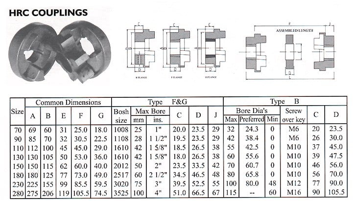
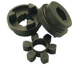
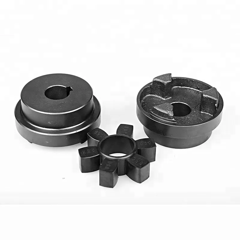
1. HRC Standard Design: The standard or classic HRC coupling design consists of two cast iron hubs with a spider made of an elastomeric material, usually rubber. The hubs have teeth on the inner surface that mesh with the spider, providing torque transmission and flexibility. This design is commonly used in various industrial applications due to its simplicity and cost-effectiveness.
2. HRC Spacer Design: The HRC spacer coupling design is similar to the standard HRC design, but it includes a spacer between the two hubs. The spacer allows for more axial misalignment compensation and can accommodate longer distances between shafts. This design is suitable for applications where additional spacing between the shafts is necessary.
3. HRC Flywheel Design: The HRC flywheel coupling design is specifically used in applications where the coupling is mounted on a flywheel. The design incorporates a flywheel mounting hub on one side and a standard HRC hub on the other side. This allows the coupling to be easily connected to a flywheel for various engine-driven machinery.
4. HRC Taper Lock Design: The HRC taper lock coupling design includes taper lock bushings that enable easy installation and removal of the coupling from the shaft. The hubs have a tapered bore, and the taper lock bushings are inserted into the bore, providing a secure and precise connection to the shaft. This design is commonly used in applications that require frequent coupling removal and reassembly.
5. HRC Brake Drum Design: The HRC brake drum coupling design is used in applications where a brake is required. The design incorporates a brake drum on one of the hubs, allowing the coupling to serve both as a torque transmitting coupling and a brake drum for braking purposes. This design is commonly used in industrial machinery where controlled braking is necessary.
6. HRC Non-Spacer Design: The HRC non-spacer coupling design is similar to the standard HRC design but does not include a spacer. This design is suitable for applications where the shafts are relatively close together, and a spacer is not required for additional misalignment compensation.
7. HRC Stainless Steel Design: The HRC stainless steel coupling design is used in applications where corrosion resistance is essential. The hubs and spider are made of stainless steel, providing better resistance to rust and corrosion. This design is commonly used in industries such as food processing, marine, and pharmaceuticals.
8. HRC Pilot Bore Design: The HRC pilot bore coupling design is supplied with plain bore hubs, allowing the end-users to machine the bore to the required size. This design is beneficial when the shaft sizes are not standard or need to be customized for a specific application.
Overall, these different HRC coupling designs offer flexibility and versatility to suit various power transmission requirements across different industries.


editor by CX 2024-04-25
by
Tags:
Leave a Reply